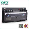
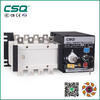
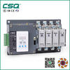
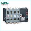
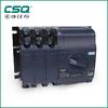
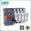
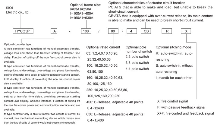
Model description
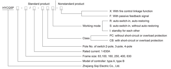
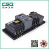
HYCQ5PA/B-250A/3,4P
Note: ①For nonstandard products, customers please indicate the detailed requirements clearly, such as form of fire control signal
(constant voltage DV24V/impulse DC24V/constant voltage AC220V/impulse AC220V, default js constant voltage DC24V if
without indication),type of passive feedback signal (position/alarm), quantity(default is one group of feedback signal)
②If there are any special requirements to the actuator circuit breaker or release, please give clear indication.
③M type represents the manual type dual-power transfer switching equipment.
Quick selection table for HYCQ5P automatic transfer switch
Function description for HYCQ5P automatic transfer switch
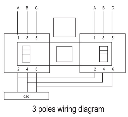
◇ Major loop wiring diagram
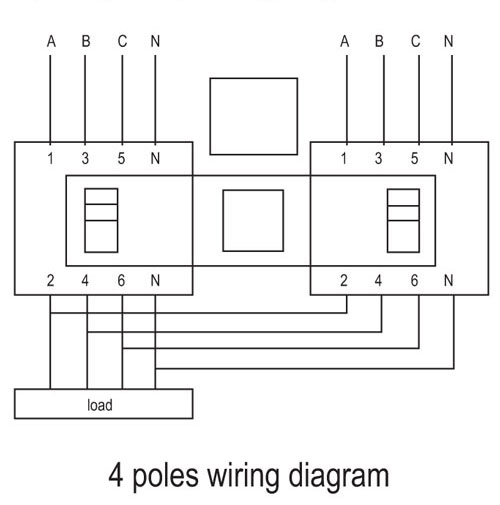
◆ Auto-switch-in, auto-restoring: when the normal power is in normal conditon, controller sends out command, normal power control
circuit breaker closes and reserve power control circuit breaker opens, automatic transfer switching equipment is at state of (1, 0).
When thenormal power is abnormal, controller will send out command, let the normal power control breaker open and reserve
power control breaker close, and the automatic transfer switching equipment is in (0,1) state. When the normal power returns to
normal, controllers will send out command, normal power control breaker closes, reserve power control breaker opens, automatic
transfer switching equipment is in (1,0) state again.
◆ Auto-switch-in, without auto-restoring: when the normal power is in normal condition, controller sends out command, normal power
control circuit breakeer closes and reserve power control citcuit breaker opens, automatic transfer switching equipment is at state of
(1, 0). When the normal power is abnormal, controller will send out command, let the normal power control breaker open and
reserve power control breaker close, and the automatic transfer switching equipment is in (0,1) state. When the normal power
returns to normal, automatic transfer switching equipment is still in (0, 1) state, only operating the button □RESET□ that can enable
the normal power control breaker to close and reserve power control breaker to open, and let the automatic transfer switching
equipment return to (1, 0) state.
◆ Standby for each other: when the normal power is in normal condition, controller sends out command, normal power control circuit
breaker closes and reserve powe control circuit breaker opens, automatic transfer switching equipment is at state of (1, 0). When
the normal power is abnormal controoler will send out command , let the normal power control breaker ioen and reserve power
control breaker close,and the automatic transfer switching equipment is in (0, 1) state. When the normal power returns to normal,
automatic transfer switching equipment is still in (0, 1) state,only when the reserve power fails that the normal power control
breaker closes and reserve power control breaker opens, and automatic transfer switching equipment returns to (1, 0) state.
◆ Command (fire control) reset (fire control command cutting off the non fire control power): No matter what state is the automatic
transfer switching equipment, once receiveing command of cutting off the non fire control power from fire control center,it would
open the normal power control breaker and reserve power control breaker of automatic transfer switching equipment, let the switch
in state (0, 0).
◆ Feedback signal: it feeds back the signal of working state of the two control breakers of automatic transfer switching equipment,
usually the signal is got from the auxiliary contact of control breaker.
◆ Power grid-powr grid: power source of automatic transfer switching equipment is from two circuits of power grid supply.
◆ Power grid-generator: power source of automatic transfer switching equipment isfrom the power grid and generator.
◆ Interconnection type: Interconnection type automatic transfer switching equipment is made up of three molded case circuit
breakers. Among them, QA and QB molded case circuit breakers are supplied by two circuits of power supply or two segments of
busbar power source separately, QC molded case circuit breaker is interconnected at output terminal of QA and QB. When any one
circuit of power source is faoled, the breaker would open, QC breaker closes, and through interconnection of this circuit breaker, the
equipment is supplied by another circuit of power source, when the fault is eliminated, the inter connection circuit breaker opens,
the trouble power circuit breaker recloses. Automatic transfer switching equipment recover snormal operation.
Functions and characteristics
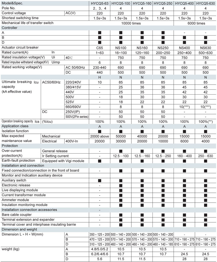
**) For operating voltage, max value can be 500V
(***) Applicable for releases of voltage class>525V Remark: H and L type molded case circuit breakers are avallable at request.
Functions and characteristics
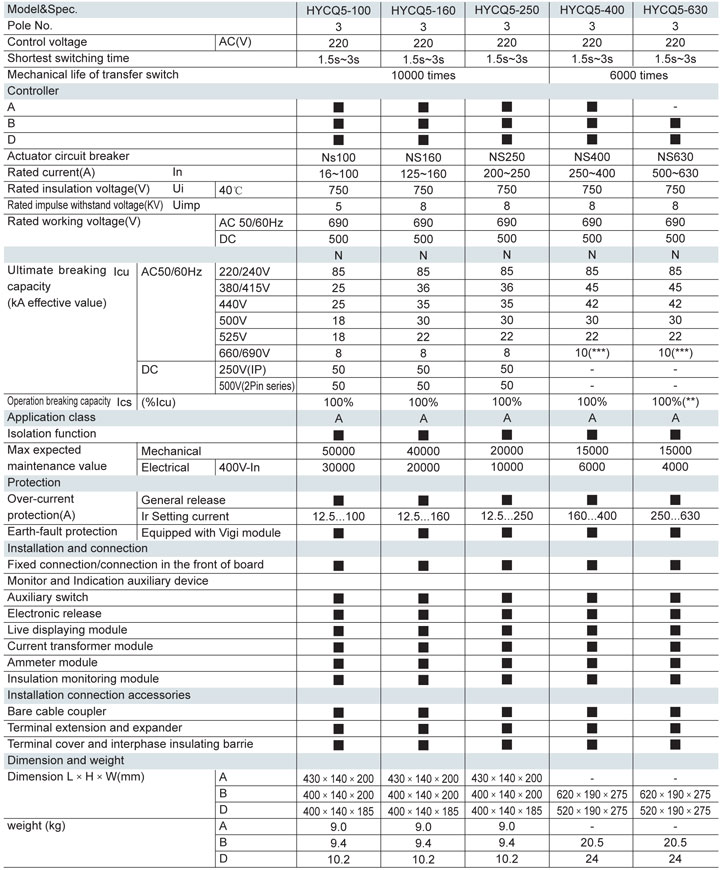
(**) For operating voltage, max value can be 500V
(***) Applicable for releases of voltage class>525V Remark: H and L type molded case circuit breakers are avallable at request.
Functions and characteristics
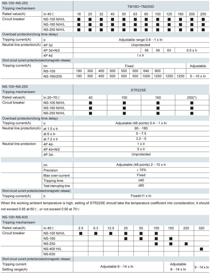
**) For operating voltage, max value can be 500V
(***) Applicable for releases of voltage class>525V Remark: H and L type molded case circuit breakers are avallable at request.
Release of HYCQ5P automatic transfer switch
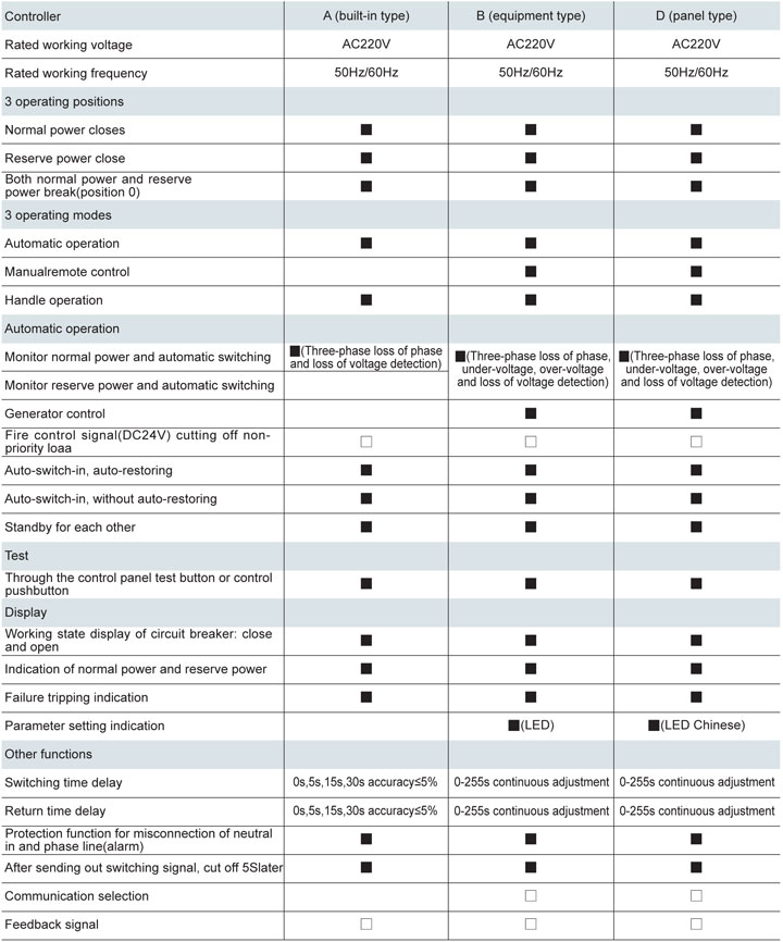
Operating sequence: A type controller
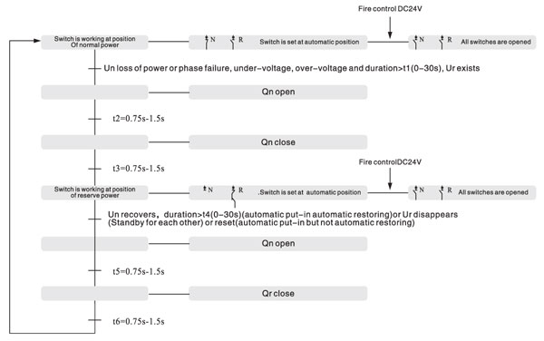
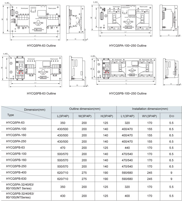
Controller of HYCQ5P automatic transfer switch
Note: ■ Standard configuration □ Optional function D type controller is of panel mode installation and can be set up on panel, it is
advantageous to the on-site monitoring, its basic functions are similar to that of B type controller, but it has LCD display and
Chinese interface and convenient site setting.
A type controller
A type controller is set inside the automatic transfer switch, whether to transfer the power is determined by the voltage condition of working power supply.
Note: "0" not represents 0s, but means the min delay time, constant time lag of system is 200~400ms.
Indicator lamp
H1 indicator lamp: always be on-normal power is normal, normal, flash-normal power is failed.
H2 indicator lamp: always be on-reserve power is normal, flash-reserve power is failed
H3 indicator lamp: lighted-normal power is closed
H4 indicator lamp: lighted-reserve power is closed
H5 lamp: lighted-normal power is over-current protected (only for NS actuator circuit breaker type switch)
H6 lamp: lighted-reserve power is over-current protected (only for NS actuator circuit breaker type switch)
.jpg)
Operating paremaeter setting of A type controller

B type controller
B type controller is located at outside of device has abundant functions
◆ Whether to transfer the power supply is determined by the operating mode of automatic transfer switch as well as condition of
operating power voltage.
◆ Start/Stop control of standby generating set.
◆ Convenient pushbutton type forced conversion by manul.
◆ Function of fire control linkage(optional module)
Outline and installation dimension drawing
Note: "0" not represents 0s, but means the min delay time, constant time lag of system is 200~400ms.
Indicator lamp
H1 indicator lamp: always be on-normal power is normal, normal, flash-normal power is failed.
H2 indicator lamp: always be on-reserve power is normal, flash-reserve power is failed
H3 indicator lamp: lighted-normal power is closed
H4 indicator lamp: lighted-reserve power is closed
H5 lamp: lighted-normal power is over-current protected (only for NS actuator circuit breaker type switch)
H6 lamp: lighted-reserve power is over-current protected (only for NS actuator circuit breaker type switch)
B type controller
B type controller is located at outside of device has abundant functions
◆ Whether to transfer the power supply is determined by the operating mode of automatic transfer switch as well as condition of
operating power voltage.
◆ Start/Stop control of standby generating set.
◆ Convenient pushbutton type forced conversion by manul.
◆ Function of fire control linkage(optional module)
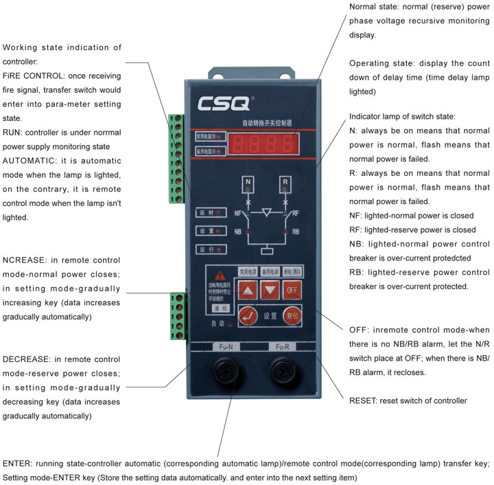
Outline and installation dimension drawing
 HYCQ5PA/B อุปกรณ์สลับเปลี...
ราคา 0.00 ฿
  แมคเนติคคอนแทคเตอร์
ราคา 250.00 ฿
  GLOQ1(G) อุปกรณ์สลับเปลี่...
ราคา 0.00 ฿
  Air Circuit Breaker - NA1
ราคา 0.00 ฿
  3SB71Z Miniature Circuit ...
ราคา 219.00 ฿
  HYCQ5P-63 Automatic Trans...
ราคา 0.00 ฿
  ATS GLOQ2-100(100A) 4 Pol...
ราคา 3,750.00 ฿
  SCB2 Polarity DC Circuit ...
ราคา 0.00 ฿
 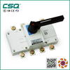 GLOG อุปกรณ์ตัดแยกโหลด
ราคา 0.00 ฿
  ATS GLOQ2-160(160A) 4 Pol...
ราคา 5,145.00 ฿


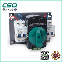
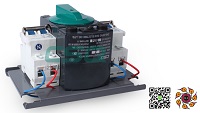


.jpg)


