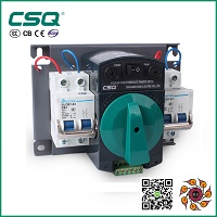
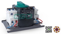
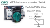
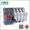
HYCQ2-125 Automatic Transfer Switching
ข้อมูลสินค้า
-
รหัสสินค้า
HYCQ2-125 Automatic Transfer Switching
-
เข้าชม
6,014 ครั้ง
ยี่ห้อ
CSQ
รุ่น
HYCQ2-125 Automatic Transfer Switching
ลิงค์
https://drive.google.com/file/d/1JZrDHlaqouM_M0EDxRNln2X7uaXaCGqL/view?usp=drivesdk
-
แก้ไขล่าสุดเมื่อ
21/06/2021 23:40
ดาวน์โหลดไฟล์ PDF
-
รายละเอียดสินค้า
ATS can only be installed in suitable locations, shall be installed, debugged and maintained by professionals, all operation, installation and wiring shall be finished according to corresponding rules in this Operating Manual, This ATS has precision structure, and has been marked before leaving the factory, don’t disassemble without authorization, or face the consequences.
General
◆ General rules
It is suitable for AC circuitry up to and including 660V and rated frequency is 50Hz, no matter it is under normal condition or fault condition, it can run safely and reliably in systems of corresponding voltage class as long as it is within the technical parameter range of switch.
Rated current of HYCQ2 type ATS include 32A,40A, 63A, 125A, 160A, 200A, 250A, 315A and 400A totally 9 specifications, all have two-pole three-pole and four-pole,and specifications 32A, 40A, 63A and 125A also have two-pole.
◆ Operating conditions
◇ Ambient temperature
a).Max temperature not exceed +40℃ ;
b).Min temperature not lower than -5℃;
c).Daily mean max temperature not exceed +35℃;
d).The manufacturer would like to settle the problem through friendly negotiation with users if the ambient temperature is beyond the range of -5℃~+40℃.
◇ Atmospheric humidity
Relative humidity at maximum temperature +40℃ shall not exceed 50%, monthly maximum relative humidity shall be 90%, it can withstand the sea damp air.
◇ Altitude
Altitude of the installation site should not exceed 2000m. If it is intended for higher altitudes, please notice that the air dielectric strength and cooling action would be weaker to some extent, the manufacturer would like to settle the problem through friendly negotiation.
◇ Class of pollution
Class of pollution of the installation site is class 3.
◇ Installation category
Its installation category is IV.
◇ Installation inclination
ATS is fixed installed in cabinet, its installation inclination should not beyond ±22.5°.
◇ Flashover distance
Flashover distance is 80mm at AC 380V, is 100mm at AC 660V, there is no necessity to consider the flashover distance for products up to 125A.
◇ Utilization category
products up to and including 400A, utilization category is AC-33B.
◇ Model description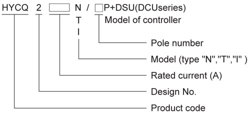
◆ Operating principle
When the voltage relay on the main power side detects voltage signal (such as no-voltage or under-voltage), voltage relay on reserve power side will act and switch on the time relay controlled by it at the same time, after time delay, switch on the intermediate relay,and supply power to its rectifier bridge, to drive the magnetic coil, then the switch acts, reserve power circuit is switched on. When the main power recovers, its voltage relay will act and supply power to the DC rectifier bridge, then the switch acts and the main power recovers power supply, meanwhile, the reserve power stops power supply.◆ Structure and function
◇ Structure
HYCQ2 type ATS adopts electromagnetic driving, simultaneous electric and mechanical interlocking mechanism, the main circuit contact is of two-static one-moving structured, the moving contact adopts "V" shaped design. In order to
avoid long term live line work of magnetic coil, type "N" ,"I" and"T" adopt double-coil DC pulse operation. After the electroma- gnetic driving, it keeps on-state by simultaneous mechanical and electric interlocking, to avoid the accident of simultaneous switch on of main and reserve power supplies. The switch body has electric or mechanical closing indicator that is used as switch status indicator;meanwhile, provides one NO one NC passive auxiliary contacts for other uses.
◇ Functions
post and telecommunication, coal mine, shipping, assembly line, medical care, military installations and so on. The main and reserve power supplies can be power grid, generator set, storage battery, etc, can be determined by users. Switching time of switch’ s main body is within 200ms, users can arrange specific time delay according to the actual situation; when the main and reserve power supplies provide power simultaneously, the main power supply has priority. The provided control schematic diagrams or schematic diagrams of the configuration DSU and DCU series intelligent controllers all have manual/automatic operating button and time-delay relay, time delay of all intelligent controllers is 0-30s adjustable, please negotiate with the manufacturer if need longer time delay.Product description
◆ Technical data and outline of N type ATS
◇ See table 1 for technical data of N type ATS.
◇ Outline and dimension of N type ATS, see Fig.l for the graphic model, see Fig.2 for the view, and table 2 lists corresponding dimensions.

Switch handle can be removed at request, total height is 110mm only.

◆ I type ATS
◇ Main functions of I type ATS:
○ Indicate the state of the current access power supply
○ Indicate the state of the current output working power supply
○ Indicate the automatic state, manual state (with powerfailure memory)
○ Realize manual/automatic transfer
○ Detect the fault state (under-voltage, over-voltage, openphase) of any one power supply automatically
○ Switch to power supply A or B by force in manual state
○ Main power can give preference to the power supply A or B
○ Control mode can be set at will:
1. Mode of auto-switch-in auto-restoring
2. Mode of auto-switch-in without auto-restoring
○ Mode of auto-switch-in auto-restoring:
When the power supply A becomes abnormal (power interruption, under-voltage, over-voltage or open-phase), it will switch to the power supply B after time delay, When A covers, the system will switch back to A automatically after time delay.
○ Mode of auto-switch-in without auto-restoring:
When both the power supplies A and B are utility power, when the power supply A becomes abnormal (power interruption, undervoltage,over-voltage or open-phase), it will switch to the power supply B after time delay, meanwhile, give an alarm; when A covers,the system will not switch back to A, but continue to supply power by B unless the power supply B becomes abnormal (power interruption, under-voltage, overvoltage or open-phase), the system will change over to A automatically after time delay.
◇ Mode setting of I type ATS (in automatic state):
○ The initial default state is “ auto-switch-in auto-restoring”mode.
○ Press the buttons “A-power manual” and “B-power manual” simultaneously for 5s,the setting mode changes from “autoswitch-in auto-restoring” to wauto-switchin without auto-restoringw,meanwhile, the manual indicator lamp flickers once.
○ Continue to press the buttons “A—power manual ” and“B-power manual” simultaneously for 5s,the setting mode changes from wauto-switch-in without auto-restoring” to“ auto-switch-in auto-restoring” , meanwhile, the time delay indicator lamp flickers once.
○ The above are cyclic operations, with indicator lamps flash circularly respectively.
○ Initial default state of main power is the power supply A, if needs to set the power supply B as the main power, just carry out in automatic mode, press “B-power manual” button for 5s,fault indicator lamp of power supply B flickers once, it means that the system has set the power supply B as the main power supply; press the“A-power manual ” button for 5s, fault indicator lamp of power supply A flickers once, it means that the system has set the power supply A as the main power supply again.
◇ Technical data of I type ATS, see table 3.
◇ See Fig.5 for outline and dimension of I type ATS, see Fig.6 for graphic model, see Fig.7 for internal wiring diagram of switch.
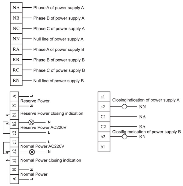
Wiring diagram
Tags : HYCQ2-125 Automatic Transfer Switching
สินค้าที่ดูล่าสุด
-
 HYCQ2-125 Automatic Trans...
ราคา 0.00 ฿
 -
 HYCQ5M-100A/3P/4P อุปกรณ์...
ราคา 9,990.00 ฿
 -
 GLOQ1B-I Automatic Transf...
ราคา 11,820.00 ฿
สินค้าและบริการที่เกี่ยวข้อง
-
 HYCQ5-63M/G/H อุปกรณ์สลับเปลี่ยนแห่งจ่ายไฟฟ้าอัตโนมัติ
รหัส : HYCQ5-63M/G/H Automatic Transfer Switching ราคา : 0.00 ฿ อัพเดท : 04/06/2024 HYCQ5M-100A/3P/4P อุปกรณ์สลับเปลี่ยนแหล่งจ่ายไฟฟ้าอัตโนมัติ
รหัส : HYCQ5M-100A/3P ราคา : 9,990.00 ฿ อัพเดท : 04/06/2024 -
 HYCQ5PA/B อุปกรณ์สลับเปลี่ยนแหล่งจ่ายไฟฟ้าอัตโนมัติ
รหัส : HYCQ5PA/B-250A/3,4P ราคา : 0.00 ฿ อัพเดท : 04/06/2024 GLOQ1(G) อุปกรณ์สลับเปลี่ยนแหล่งจ่ายไฟฟ้าอัตโนมัติ
รหัส : GLOQ1(G)-32-800A/4P ราคา : 0.00 ฿ อัพเดท : 04/06/2024 -
 GLOQ1 อุปกรณ์สลับเปลี่ยนแหล่งจ่ายไฟฟ้าอัตโนมัติ
รหัส : GLOQ1-100,3200A/4P ราคา : 0.00 ฿ อัพเดท : 04/06/2024 -
 GLOQ1B-T automatic change over…
รหัส : GLOQ1B-T automatic changeover switch ราคา : 19,980.00 ฿ อัพเดท : 18/03/2024 HYCQ2-125 Automatic Transfer Switching
รหัส : HYCQ2-125 Automatic Transfer Switching ราคา : 0.00 ฿ อัพเดท : 21/06/2021 -
 HYCQ5P-63 Automatic Transfer Switching
รหัส : HYCQ5P-63 Automatic Transfer Switching ราคา : 0.00 ฿ อัพเดท : 22/03/2020 -
 ATS GLOQ2-100(100A) 4 Pole.
รหัส : CSQ Automatic Transfer Switch GLOQ2-100A 4 Pole. ราคา : 3,750.00 ฿ อัพเดท : 28/08/2019 -
 ATS GLOQ2-125(125A) 4 Pole.
รหัส : CSQ Automatic Transfer Switch GLOQ2-125A 4 Pole. ราคา : 4,200.00 ฿ อัพเดท : 28/08/2019 ATS GLOQ2-160(160A) 4 Pole.
รหัส : CSQ Automatic Transfer Switch GLOQ2-160A 4 Pole. ราคา : 5,145.00 ฿ อัพเดท : 28/05/2024


